Clock and Memory
Created by Masashi Satoh | 12/7/2025
- Shaping the spine of the ICT curriculum in Waldorf education
- The History of Computers(Currently being produced)
- Details on Constructing an Adder Circuit Using Relays
- Internet
- Learning Data Models
- Learning Programming and Application Usage Experience(Currently being produced)
- Human Dignity and Freedom in an ICT-Driven Society(Currently being produced)
Introduction
This article supplements the main section “Detailed Construction of a Relay-Based Adder Circuit.”
The importance of memory circuits in computers goes without saying. On the other hand, the clock circuit itself is merely an oscillator. Nevertheless, I believe it is a crucial mechanism that enables the complexly intertwined components to synchronize and generate the overall operation. As an element that brings the dynamism of an automatic machine to computers, I consider it highly valuable for students to learn.
By learning these two elements as a pair, we can introduce the perspective of polarities—dynamic and static, change and preservation—into the inorganic device that is the computer. In this sense, I believe this learning is profoundly meaningful. It is not merely about learning clock signals and memory device mechanisms; it provides students with an image that breathes vibrant life into the entire study of computers.
And above all, it’s an excellent learning experience because it allows you to grasp the essence of these two mechanisms through a very simple experiment: simply adding feedback to the Buffer circuit and NOT circuit you’ve already built.
Negative Feedback Circuit and Clock
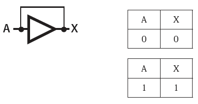
First, draw a NOT circuit on the blackboard. Then create a truth table and review the properties of the NOT circuit.
Next, tell the students:
“What happens if we feed the output of this NOT circuit back into its input?”
Then conduct a thought experiment using the truth table on the blackboard.
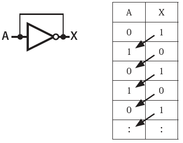
“If the initial value of input A is 0, the output X is 1. If we feed that back as input, A becomes 1, so X becomes 0. If we feed that back as input, A becomes 0, so X becomes 1. This should repeat endlessly, causing X to oscillate between 0 and 1.”
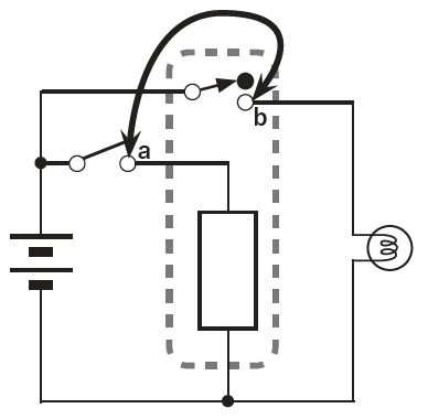
“Now, let’s actually build this circuit using a relay NOT circuit.”
Using the workbench, first build a NOT circuit. Then create a truth table and verify its operation.
Next, confirm where the NOT logic’s input and output correspond to actual components in the device. The relay’s coil L terminal corresponds to the input, while the NC terminal connected to the LED corresponds to the output.
Once this is confirmed, remove the bulldog clip from Switch A and proceed with the actual wiring. You should then hear a series of beeps accompanied by small cheers from various places.
After observing for a moment, I tell the students to carefully observe what is happening. Then, they usually give answers like the following.
- The relay is shaking and making noise.
- The relay’s switch part seems to be vibrating at high speed.
Taking up that point, I use the relay sketch on the blackboard (which I’ve drawn in advance) to explain what’s happening and confirm that it’s a concrete representation of the changes in X in the truth table. This isn’t a particularly difficult task. Then I confirm it further.
“If it’s as shown on this blackboard, wouldn’t the LED also be turning on and off?”
The students look like they think that might be the case, but based on observation, the LED doesn’t appear to be blinking.
Then, I take out a rod with an LED attached to its tip and connect it to the student’s circuit. After making the circuit oscillate, I demonstrate swinging the rod. Sure enough, the LED’s trajectory should appear to flash.

Because the human eye retains afterimages, the LEDs appeared to be continuously lit.
Based on this experience, explain to the students that this principle is used in the clock signal that drives a computer’s operations.

Since computers perform complex calculations by combining many mechanisms, the clock serves as a timing signal to synchronize these mechanisms. It’s similar to how the rowers in a cutter boat must row in unison with the coxswain’s commands to move forward smoothly.
“Next! Next!”
Use gestures to help students visualize the computer’s operations progressing rhythmically. Emphasize that this clock signal is what drives the computer’s movement. This mental image will prove valuable later in the sequencer experiment.
Another way to observe the LED flashing is to increase the delay in the negative feedback circuit. Since there are three relays on the workbench, create a NOT circuit with the first one and cascade the remaining two as buffers. By forming a feedback loop with these three relays, you can observe the relays flapping and the LED flashing.
However, this approach increases complexity and slightly blurs the focus, so I recommend the method mentioned earlier.
Positive Feedback and Memory Circuits
So, what happens when we apply feedback to the buffer circuit?
As before, let’s first conduct a thought experiment on the blackboard.
If the initial value of input A is 0, output X is 0. Even if you feed that back into the input, output X remains unchanged. The same holds true if the initial value of A is 1.
What possible use could such a thing have?
Here, we explain that this is used as memory—that is, to retain information. There’s no need to go into detail. Let’s get straight to the experiment.
Simply swap one wire in the NOT circuit already assembled on the workbench to create a buffer circuit. Then, create a truth table here as well to confirm it functions as a buffer circuit.
Remove the bulldog clip from Switch A and connect the output to the input. The procedure is the same as the previous experiment.
Now, let’s turn Switch A ON. The LED lights up. Next, turn the switch OFF. That is, remove the bulldog clip.
At this point, several students who notice something unusual should speak up. What happened?
Even after removing the switch, the LED does not turn off.
The teacher accurately captures the student’s sense of surprise and explains that this means the information has been retained. With just this, students gain an experiential understanding of what a memory device actually is.
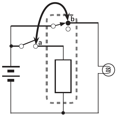
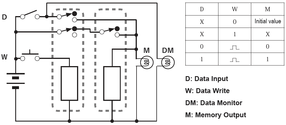
If the instructor has time, it would be even more effective to assemble a memory device with a data write switch added to the workbench beforehand and demonstrate its operation.(See the column below)
Once the students have gained a deep understanding of what a memory device is, the teacher directs their attention to how the positive and negative aspects of the feedback loop generate the opposing functions of motion and stillness, movement and retention.
Within the overall flow of the lesson, seize an appropriate moment to explain that while ENIAC used 640 memory units (80 bytes), even a standard home PC in 2025 now incorporates 8 billion of them. This was made possible by photoresist technology, which enables microfabrication precise enough to etch 1,000 lines onto a surface as thin as a strand of hair.
After this lesson, showing students a diagram of a buffer circuit with a return signal will enable them to recall how memory circuits function.
The circuit diagram for the memory device with the added data write switch is shown below. Note that this circuit utilizes the significant delay inherent to relays, so it is unlikely to function with semiconductor logic devices.
In closing
As already mentioned, in the study of a certain egoistic computer technology that imposes human thought onto phenomena, this section — which allows us to confront the phenomena arising from the polarity of return — is a beloved learning experience, like encountering a clear spring of water along the journey.
In this way, students can experientially learn about the two crucial elements that drive a computer: the clock and memory.
Learning about the clock helps visualize the dynamic operation of a computer and, as the element that determines its computational speed, also aids in imagining the immense processing power of modern computers.
This visualization will prove highly useful in the experiment connecting the adder and sequencer.
Learning about memory is no different. I believe students’ understanding of computers changes significantly depending on whether they have such concrete experiences or not.
These lessons are conducted in conjunction with telegraph experiments, following the study of implementing AND and OR circuits using relays, and preceding the study of adders. The negative feedback oscillator circuit can be effectively utilized as a buzzer substitute during the telegraph device construction practical.
When negative feedback is applied to a relay’s NOT circuit, it oscillates because, in the case of relays, the output reacts very slowly to changes in the input. The smaller this delay becomes, the higher the oscillation frequency rises, but eventually the amplitude decreases and it begins to function as an inverting amplifier.
In terms of being sensitive to small movements, amplifiers retain the same dynamic properties as oscillators.
One mechanism utilizing the characteristics of positive feedback is the hysteresis circuit, which is used for applications such as chattering suppression. This circuit leverages the holding effect, where once the mode switches, it resists easy changes to the mode.
All memory, including magnetic storage devices, utilizes this hysteresis property to retain its state.
The motion of negative feedback can be understood by imagining a balancing toy—like a yajirobe. The motion of positive feedback is easier to grasp by imagining square building blocks.

- Shaping the spine of the ICT curriculum in Waldorf education
- The History of Computers(Currently being produced)
- Details on Constructing an Adder Circuit Using Relays
- Seesaw Logic Elements
- Clock and Memory
- The Origin of the Relay and the Telegraph Apparatus
- About the sequencer
- About the Battery Checker(Currently being produced)
- Internet
- Learning Data Models
- Integer type
- Floating-point type
- Character and String Types
- Pointer type
- Arrays
- Learning Programming and Application Usage Experience(Currently being produced)
- Human Dignity and Freedom in an ICT-Driven Society(Currently being produced)